How accurate is TDoA?
The certainty of a signal's estimated location can be as high as meters or as low as kilometres. Where you are on this sliding scale depends on the signal itself, how the whole system is implemented, and where the system is deployed.
TDoA can provide highly accurate geolocation results in real time. The methodology works well with low-power signals and also in urban environments where multipath effects are prevalent. The network of sensors deployed uses simple omnidirectional antennas and can be static or mobile. TDoA systems are flexible and even work where no GNSS (Global Navigation Satellite Systems) data is available. However, they must be installed and operated based on important considerations.
How does TDoA work?
To set up a TDoA measurement, a network of sensors is positioned around the area where a signal is expected to be emitted. The sensors should be well separated from each other, ideally with the source in the centre. Therefore, simple geometries (e.g. a triangle) are good candidate formations for TDoA. To understand why, we must consider how TDoA works.
In TDoA, the deployed sensors are used to form pairs. When both sensors in a pair detect the same signal, the time difference provides a constraint on the signal's location. Unfortunately for a single pair, the mathematical solution shows a curve (known as a hyperbola) rather than a single point in space, as there are many solutions to the equation.
The image below shows two sensors and a corresponding curve. The signal could have been emitted anywhere along this curve; therefore, one pair cannot be used to locate a signal accurately.

Image 1: Two sensors and the corresponding curve
Accurate signal geolocation requires multiple sensor pairs to determine the source. Each pair gives a curve showing possible locations, and combining several of these curves from different pairs allows us to pinpoint the signal's location. At least three sensors are needed to form three pairs. For wide-area coverage, the most effective setup is to place the sensors in a roughly equilateral triangle.
A signal can be located in either two dimensions (latitude, longitude) or three dimensions (latitude, longitude, elevation). For 2D-TDoA, at least three sensors are required, while for 3D-TDoA, this minimum increases to four. Still, other considerations may increase the required number of sensors for accurate geolocation.
The image below shows four sensors in a triangle formation (plus one in the center). Curves are formed from pairs of sensors, and the target signal is located where the curves intersect.

Image 2 shows a network of four RF sensors geolocating an airborne target using 3D TDoA.
The TDoA algorithms look for a unique feature in the signal received. Once they locate the time that feature is seen in each pair of sensors, an arrival time difference can be calculated. Mathematically, this time shift is calculated using a cross-correlation function. If the signal has narrow, clearly defined peaks, then the calculation of the time offset will have less error, as there is a clear peak to line up. However, if the peak is wide, a larger error will result as there is a greater time where the peaks could overlap.

Image 3: A feature with a narrow peak has a smaller error when aligning the two signals. If the peak is wide, the alignment could happen over a larger period, thus increasing the error.
The ideal signal for TDoA is a wideband, modulated, non-random, non-repeating signal. Each of these characteristics allows for a more precise time alignment of the signals received, making the process more accurate and less ambiguous.
Wideband signals have higher data rates, which means there are more features for the algorithm to detect and align. Modulated and non-random signals have known structures, which can make it easier to detect features. If the signal has repeating sections, the features used for alignment will appear more than once, giving more than one time difference.
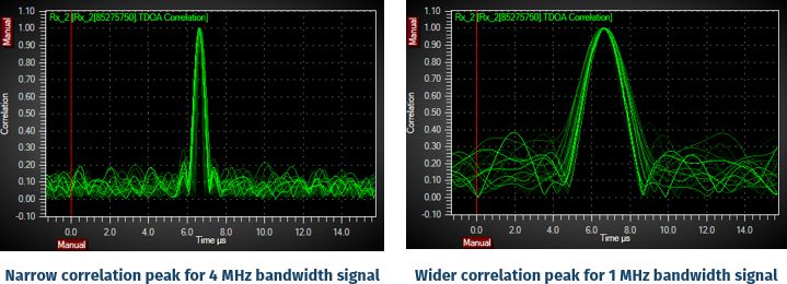
Image 4: The correlation peaks for a 4 MHz bandwidth signal and an equivalent 1 MHz bandwidth signal. The narrower a signal's bandwidth, the wider its peak will be.
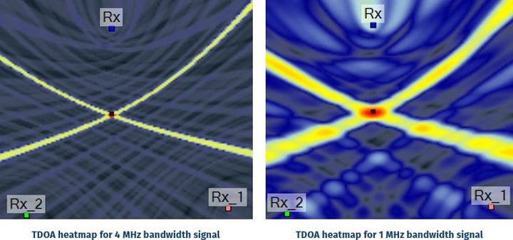
Image 5: The wider correlation peak corresponds to greater uncertainty in the time delay and, hence, in the location. (Simulation in RFeye Site)
What impacts the accuracy of TDoA?
The factors that impact the accuracy of TDoA can be grouped into three categories: external factors, signal characteristics, and RF sensor configuration.
The relative impact of each factor will vary depending on the specifics of your installation. In other words, the primary source of error in one deployment may be different in another—accuracy is context-dependent.
External factors
For TDoA to work effectively, each sensor must have a clear line of sight to the signal source. If the signal path is obstructed—by terrain features like hills or buildings—the signal may be weakened, delayed, or completely blocked.
When a sensor lacks line-of-sight, it cannot reliably participate in the TDoA calculation, which can reduce geolocation accuracy.
Image 6 (below) shows how a sensor blocked by a building is unable to receive the signal from the source, making it unusable in the TDoA network. However, repositioning the sensor (placing it on top of the building) restores line-of-sight, enabling it to receive the signal and be part of the TDoA geolocation.

Image 6: Image showing how changing the position of a sensor can improve TDoA accuracy.
An ideal location to deploy a TDoA sensor network is a perfectly flat area with no hills, buildings, or other electromagnetic signals to cause obstruction. However, even this scenario is constrained by scale as the curvature of the Earth will eventually hide the sensors from one another, limiting the effective range of a single TDoA installation.
Systems deployed in a real-world environment must accommodate local geography and man-made structures. If one sensor is hidden, it can be moved to the top or side of the obstruction. If this is not possible, additional sensors can be added to the network to cover the gap caused by the obstruction. Conducting an analysis of the area before sensor deployment allows for optimal sensor placement, ensuring sufficient coverage and accurate geolocation.
Another important factor is multipath effects, which are caused by reflected and diffracted copies of a signal from features like local terrain, buildings, hills, etc. These create copies of the signal that travel different distances and are received at slightly different times—broadening the peak of the alignment feature, which increases error.
The good news is that TDoA is relatively robust against multipath effects, thanks to advanced signal processing algorithms. Also, with proper planning and deployment, these effects can be further mitigated.

Image 7: Multipath signal bounces from local obstructions.
Analysis using LiDAR (Light Detecting and Ranging) or SRTM (Shuttle Radar Topography Mission) elevation data can help build a picture of the expected multipath signals caused by the terrain. Comprehensive terrain profiling can be carried out using modelling tools in RFeye Site, which provides a deep understanding of the expected multipath signals and the ability to account for them using multipath mitigation algorithms.
The same principle applies to buildings (or any static object) in urban areas, so long as their impact on signal propagation is understood. Simulation tools are invaluable for evaluating sensor layouts in a virtual environment, allowing for refinements before physical deployment, where changes are significantly more costly. Moving objects can also be accounted for, but this is more difficult as their effect on the system moves with them.
Another mitigation that will help solve both line-of-sight and multipath effects is to position sensors at different elevations. This is a requirement for 3D-TDoA and can help improve the accuracy of any system.
A final consideration before establishing sensor locations is the practical support infrastructure each sensor requires. This includes access to power, reliable data transmission for analysis, environmental protection, and physical accessibility for installation and maintenance. In systems that do not rely on GNSS for timing, additional requirements may include physical cabling between sensors to maintain synchronization.
Signal characteristics
A signal needs to be strong enough to be received and received for long enough for the sensors to collect key features for alignment. This is primarily determined by the signal-to-noise ratio (SNR). Ideally, signals would be high-powered, and there would be low background noise. However, in practice, environmental noise and interference regularly degrade signal quality. A low SNR makes the alignment difficult as the features are blurred, making accurate TDoA calculation more difficult.
The good news is that accurate geolocation is still possible for signals below the noise floor, provided the right measures are in place. For example, using highly sensitive sensors and advanced signal processing techniques can significantly reduce geolocation error, even in low-SNR environments.
If the signal is noisy, the features are degraded, making alignment more challenging. However, noise is unavoidable in real-world environments. TDoA systems mitigate this by collecting multiple measurements and averaging them, which helps reduce the impact of errors in any single reading and improves overall accuracy.
When a signal originates from within the sensor network, it results in the lowest positional uncertainty. Signals located outside the network can still be geolocated, but with reduced accuracy. In certain scenarios—particularly when signal strength is low or line-of-sight is obstructed—detection may not be possible at all.

Image 8: Two location probability heat maps for transmissions inside and outside an RF sensor network. The larger, red area for the transmission in the right-hand image indicates a greater uncertainty in location. (Simulation in RFeye Site)
Detection accuracy outside the network can be improved by using highly sensitive RF sensors with a high dynamic range, combined with advanced software techniques such as digital adaptive filtering. In scenarios where out-of-network detection is expected, performance can be further enhanced by deploying high-gain directional antennas and mobile nodes to help locate the signal.
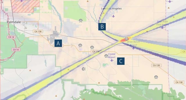
Image 9 (below) shows how highly sensitive sensors can geolocate ADS-B signals approximately 400 km outside the sensor network. This is a real-world deployment in Buffalo, New York, USA. Sensors are located at each point of the yellow triangle, with one in the center of the triangle. While the most accurate 3D TDoA geolocations are within the network (which has a 75k baseline), signals can reliably be detected well outside the network.

Image 9: A deployment in Buffalo, New York, detecting ADS-B signals approximately 400km outside the sensor network.
RF sensor configuration
A final critical factor is synchronization between sensors. Even minor clock discrepancies can result in significant positional errors. To ensure precise alignment, sensors use high-stability clocks synchronized via Global Navigation Satellite Systems (GNSS), such as GPS. This approach requires reliable GNSS reception at each sensor location and is a cost-effective solution, as no additional hardware is required to synchronise the clocks.
However, in situations where GNSS is unreliable, vulnerable to disruption (e.g., solar flares), or cannot be used due to operational constraints, there are alternative synchronization solutions.
In scenarios where only temporary GNSS outages are expected, a holdover system can be used to maintain clock alignment. CRFS offers a dedicated Holdover module in its RF sensors for this purpose.
The GNSS holdover module ensures that the RFeye Node maintains a precise timing reference even if its internal GNSS chipset is jammed. It enables operators to continue geolocation tasks by providing precise timing within 1.5 µs for up to eight hours.
After having established its timing reference (which takes four to five days), the RFeye Node seamlessly switches between GNSS and the holdover module based on the availability of a reliable GNSS signal. With the holdover module, military forces can carry out TDoA geolocation to pinpoint and neutralize the jamming source, thereby restoring GNSS functionality.
In systems where GNSS cannot be used or outages are unacceptable, a direct synchronization link between nodes is required. This typically involves a cabled connection that provides continuous, high-precision clock alignment across the network. CRFS offers the SyncLinc system to support this capability, delivering uninterrupted synchronization with geolocation accuracy within tens of meters.
Conclusion
This article has reframed the question “How accurate is TDoA?” with the more poignant consideration “What can I do to ensure the most accurate TDoA?” While several tactics can improve the accuracy of a TDoA network, the overall geolocation accuracy is limited by the factor causing the worst error.
Therefore, it is important to assess what factors can cause errors when designing a system. Using simulation software to calculate optimal sensor positioning and propagation analysis will help optimise the TDoA network, understand the effects of errors, and mitigate them before investing in a real-world deployment.