Why radio frequency (RF) matters
In 1897, Scientific American criticized Guglielmo Marconi’s radio wave device. “If the invention was what he believed it to be, our mariners would have been given a new sense and a new friend which would make navigation infinitely easier and safer than it now was.”

Although electromagnetic radiation and radio frequency was not a new concept, Marconi was the first to realize the commercial possibilities of the discovery.
Today, wireless technology is ubiquitous in the military and civil society; it connects people and systems and is the universally accepted way to transfer large amounts of data across (almost) unlimited space. We have become entirely dependent on wireless devices sending radio signals across the ElectroMagnetic Spectrum (EMS): mobile telephony, Radar, broadcast radio, Bluetooth, Wi-Fi, and the IoT are all examples of technologies completely reliant on radio frequency (RF) transmission.
RF matters because it is critical for today’s electronic devices—the foundation of our modern, wirelessly-connected lives. RF technology allows us to work, controls our transportation, and keeps us safe.
Our dependency on and thirst for bandwidth, driven by our information-based society, presents challenges as the EMS becomes crowded. A crowded spectrum can cause electromagnetic interference, leading to consequences ranging in severity—anything from missing a touchdown in the Super Bowl to a catastrophic military loss.
Our increased usage is causing a dearth of available EMS on a local, national, and international level. Although the EMS is theoretically infinite, there are limits to the useable spectrum available due to a) physical factors constraining operational range and b) the technological capability we have available for its exploitation.
If we wish to continue scaling up our use of the spectrum, it must be used more efficiently and governed in the interest of all citizens. For short-range applications, management can be affected simply by localized spectrum managers, or by using adherence to common sharing protocols such as are standardized for Wi-Fi devices. However, longer-range applications can be more challenging as national bodies must coordinate for smooth and efficient spectrum sharing. The situation becomes more complex near international borders, where authorities from different countries must agree upon and coordinate spectrum use.
The electromagnetic spectrum and RF
The electromagnetic spectrum and RF
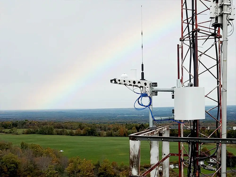
What is the electromagnetic spectrum? Waves in the electromagnetic spectrum (EMS) travel at 300,000 km/s—the speed of light. Some EM Waves, such as the colors in a rainbow, are visible to the human eye, but most types of EM waves are not. Radio waves are one example of an EM wave that is invisible to humans.

In addition to power, there are two parameters of EM waves that we can measure. Frequency: the number of waves that pass by a given point in one second (measured in cycles per second or Hertz) and wavelength: the distance from the peak of one wave to the peak of the next (measured in fractions of a meter). Note there is an inverse relationship between frequency and wavelength—the larger the frequency, the smaller the wavelength.
Specifically for radio frequency, the EMS is the range of frequencies used for wireless communication.
What is RF transmission?
Radio frequency (RF) transmission is electromagnetic radiation that is used to transmit data wirelessly through a range of frequencies. RF energy is ubiquitous in many electronic devices such as cell phones, radios, and televisions.
How does RF transmission work?
RF allows data to be transferred by measuring modulation of the radio spectrum in frequencies ranging from a few Hz to the lower limit of infrared: 3Hz (ELF) to 300GHz (EHF). Radio waves are transmitted and measured in several areas, mainly communications and medical treatments.
What is RF transmission used for?
RF energy is used in many different applications, including broadcasting, telecommunications, satellite communication, and wireless networking. Moreover, RF transmission enables vital military communications systems, intelligence, surveillance, and reconnaissance (ISR) systems, and electronic warfare (EW) suites.
How is RF energy measured?
RF energy is generally measured in watts (W) or milliwatts (mW). The amount of energy in a radio wave is determined by its peak power, or the highest amount of energy it can attain. A power meter can measure the power of an RF wave to determine the energy it carries. Additionally, various types of probes and sensors can measure different types of RF energy, such as continuous wave (CW) or pulsed RF energy.
What is spectrum management?
Spectrum management is the process of regulating the use of the radio frequency spectrum. The goal is to ensure that all wireless communication technologies can coexist, minimizing interference, maximizing efficiency, and eliminating unauthorized resource use.
There are three key areas of spectrum management. First, the process involves allocating specific frequencies and assigning them to particular uses, such as broadcasting, cellular networks, satellite communication, and other wireless services. Second, it entails establishing technical standards for wireless devices and ensuring they comply with them to avoid interference with other devices. Third, it includes monitoring and enforcing compliance with regulations to ensure that wireless services operate within their allocated frequency bands.
Effective spectrum management is essential to ensure that wireless communication networks operate efficiently and reliably. This should promote innovation and investment in new technologies and support the growing demand for wireless services.
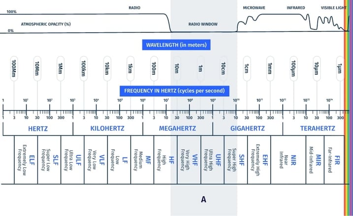
Figure 1: Radio spectrum frequencies and corresponding usage
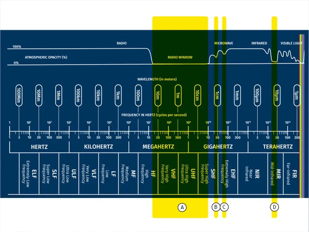
(Source: CRFS)
Figure 1 highlights the band within which most high-frequency licensed communications operate, free from significant atmospheric absorption.
What is RF spectrum monitoring?
RF spectrum monitoring is the process of detecting, measuring, and analyzing radio frequency (RF) signals. The information gathered through RF Spectrum Monitoring can be used to identify sources of interference, optimize antennas and receivers, and identify potential spectrum issues.
The overarching goal of spectrum monitoring is to support the spectrum management process. The more specific goals are to:
- Address and prevent EMS interference
- Ensure a minimum standard for wireless services (such as acceptable television and radio reception, mobile coverage levels for a percentage of the general population and wireless coverage for emergency services)
- Provide important spectrum monitoring data to administrative organizations
Spectrum planning and allocation
Spectrum planning is the challenge of allocating the RF spectrum to different radiocommunication services on an exclusive or shared basis. Internationally, this distribution is governed by World Radiocommunication Conferences (WRC). Based on the International Table of Frequency Allocations, national bodies can organize their own frequency allocations.
Figure 2. United States Frequency Allocations – The Radio Spectrum
Click the image to see an enlargeable format
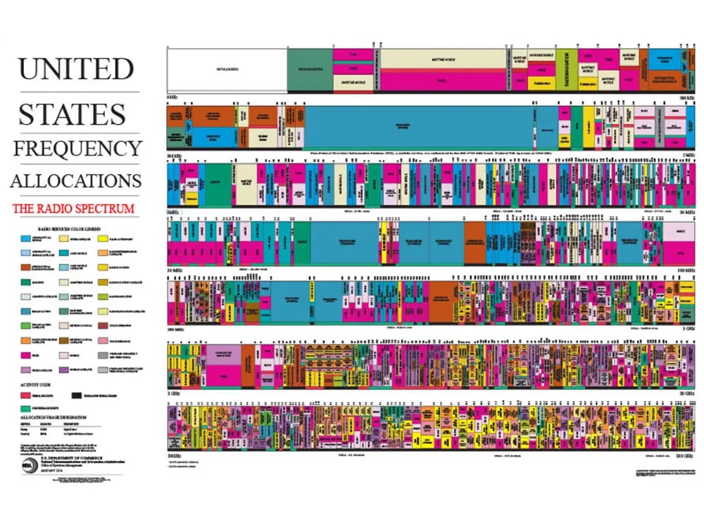
(Source: US Department of Commerce)
Spectrum sharing
Users sharing a segment of spectrum frequency is a crucial part of spectrum management. Efficient sharing means more spectrum is available for more users and is facilitated by national bodies working together and international organizations coordinating near border regions.
National bodies must follow the allocation table when assigning appropriate frequencies. Technical procedures of frequency assignment should allow effective channel and frequency re-use based on possible interference concepts or necessary frequency-distance separation criteria between radio networks.
Figure 3: Spectrum licensing mechanisms
- INDIVIDUAL SPECTRUM LICENCES: Operator allocated
- APPARATUS LICENSES: Type of equipment in use
- UNLICENSED SPECTRUM: Nonexclusive – e.g. Bluetooth & Wi-Fi
However, managing the spectrum closer to international borders is more challenging because different countries generally have different rules and regulations regarding the allocation and use of radio frequencies. As a result, frequency usage must be coordinated in border areas, where the same frequency may be allocated to different services, as there may be interference when multiple signals from different countries overlap.
As spectrum allocation is a political decision, when political tensions exist between neighboring countries, there may be a lack of cooperation or disagreements over the use of specific frequencies. This can lead to delays or difficulties in negotiating agreements on spectrum usage.
There is also a military aspect of spectrum allocation. When a unit is mobilized to a foreign region, they must ensure they follow local allocation rules. In this scenario, military spectrum managers are essential in planning and executing field operations.
Figure 4: Technologies driving spectrum demand
- 5G SPECTRUM: Increased penetration of 5G technologies
- INCREASING USE OF IOT: More connected devices, from washing machines to coffee machines
- EVOLUTION OF WI-FI: Increased usage of Wi-Fi enabled devices
- HAPS CONNECTIVITY: International exploitation of High-Altitude systems
- NGSO SATELLITES: Growing applications for non-geostationary satellite
Historic RF milestones
From the first experimental radio transmissions in the late 1800s to a society that is now dependent on wireless communication systems: RF technology has come a long way. The advancements in this field have been driven by innovation and discoveries, resulting in numerous historic milestones.
1887 – Heinrich Hertz demonstrates the existence of radio waves, proving that electromagnetic waves can be transmitted through the air. Although Hertz was not the first to produce radio waves, he was the first to understand they were electromagnetic.
1895 – Guglielmo Marconi built (and then marketed) the first wireless telegraphy system. Marconi’s system used RF waves to transmit signals wirelessly over long distances. He developed a transmitter that could convert electrical signals into radio waves and a receiver that could detect those radio waves and convert them back into electrical signals.
1901 – Marconi sends the first wireless message across the Atlantic Ocean, ushering in a new era of global communication.
1906 – Reginald Fessenden made the first long-range radio transmission of voice and music from Brant Rock to ships sailing along the Atlantic coast.
Fessenden's radio broadcast used an electrical signal from a microphone to modulate the carrier wave, which was then transmitted as an RF wave. The RF wave was picked up by receivers tuned to the same frequency and demodulated to recover the audio signal.
c. 1930 – Pre-World War II, several countries started developing radar technologies: radio waves sent from an antenna that bounce off objects they encounter.
The reflected signal can be used to determine the location and speed of the object. Work on radar undertaken in the 1930s by Robert Watson-Watt in the UK and Christian Hülsmeyer in Germany played a critical role in detecting enemy aircraft and ships.
1957 – Sputnik 1 was the first artificial satellite sent to orbit around the Earth (by the Soviet Union).
Satellite communications use RF to transmit signals carrying information between the satellite and the ground station or another satellite.
1964 – The Syncom 3 satellite was launched by NASA. It was an experimental communications satellite designed to demonstrate the feasibility of using satellites in geostationary orbit for global telecommunications.
1969 – Apollo 11 made the first moon landing. The spacecraft and the space station used RF to communicate, even when the spacecraft was on the far side of the moon out of line-of-sight control. The spacecraft used an S-band radio frequency to transmit data back to Earth, while the ground stations used an X-band frequency to send commands to the spacecraft.
1973 – Martin Cooper, an engineer from Motorola, invented the technology upon which the first mobile phone was built. However, it wasn’t until 1984 that Motorola released their DynaTAC—affectionately known as ‘the brick’.
The RF technology in mobile phones uses radio waves to communicate between devices. Mobile telephones send RF signals to nearby cell towers, which transmit the signal to the recipient’s cell phone. The signal is converted into sound waves, allowing the receiver to hear the caller’s voice.
1977 – The first live human was given an MRI scan. Magnetic Resonance Imaging was invented in the early 1970s by Paul Lauterbur and Peter Mansfield; the technology uses RF waves to generate images of the body’s internal structures.
MRI machines generate a strong magnetic field, aligning hydrogen atoms in the patient’s body. It then emits RF waves causing the hydrogen atoms to emit energy, which is detected by the MRI machine and used to create images of the body.
1993 – The full Global Positioning System constellation of 24 satellites became operational in 1993. GPS uses a network of satellites in orbit around the Earth to determine a user’s location. Each GPS satellite transmits a signal with a unique code and timing information. By receiving signals from multiple GPS satellites, a GPS receiver can calculate its position by measuring the time delay between the transmission of a signal and its reception.
The signals transmitted by GPS satellites use RF as the waves can travel long distances through the atmosphere and are able to penetrate clouds, foliage, and buildings.
c. 2003 – Internet of Things (IoT) technology became prevalent thanks to the development of low-cost sensors and the widespread availability of wireless networks. RF is crucial for IoT technology as it enables wireless communication between these devices.
2019 – The first 5G commercial network was launched in South Korea. 5G technology uses RF waves to transmit data wirelessly between devices and cellular towers, but it uses higher frequencies than previous generations of wireless technology, allowing faster data transfer rates, lower latency, and greater network capacity, making it possible to support more connected devices and applications.
RF fundamentals – key terms
Understanding RF fundamentals is crucial to operate and maintain modern wireless systems. The following are commonly used radio frequency terms. However, there might be nuances in the use of certain terms depending on their context and application.
Angle of Arrival (AOA): a concept used to determine the direction from which a signal is transmitted. Multiple antennas are used to receive a signal from a transmitter. Antennas are positioned with different views of the incoming signal, and the difference in the arrival time and phase of the signal at each antenna is used to calculate the signal's arrival angle.
Antenna: a device that transmits or receives radio waves. To transmit, an antenna converts an electric current into radio waves, and it does the opposite to receive. Different antennas are used to send and receive at different frequency ranges.
Array: two or more antennas arranged to create a directional receiving pattern or arranged to allow measurement of phase difference between the antennas. An array can be used to create a line of bearing toward an RF transmission source.
Bandwidth: the range of frequencies within the spectrum that can be used for a particular communication system to transmit information without significantly losing quality.
Center frequency: the specific frequency at which a radio signal or other form of electromagnetic radiation is transmitted or received. The center frequency is the midpoint or measure of the central frequency between the upper and lower cut-off frequencies (signal frequency range).
Decibels (dB): a unit of measurement used to express the ratio between two values, typically the ratio of two power or amplitude levels. The decibel scale is logarithmic, meaning that a change of one decibel corresponds to a multiplication of the quantity being measured by a constant factor.
Decibel-milliwatt (dBm): a unit of measurement used to express the power of an electrical signal in decibels (dB), relative to 1 milliwatt (mW).
Demodulation: the process of extracting information from a modulated RF carrier signal. RF signals are often modulated to carry information, such as voice, video, or data’ therefore, demodulation is necessary because the information carried by the modulated RF carrier signal cannot be directly accessed or decoded. Demodulation recovers the original information signal by removing the carrier signal and extracting the modulating signal.
Dynamic range: the difference between the weakest and strongest signals that a system can detect and monitor. The dynamic range for an RF monitoring system is the difference between the noise floor and the strongest signal.
Gain: the ratio of an amplifier device’s output power to the input power, expressed in dB.
Gigahertz (GHz): a unit of measurement for RF wave frequencies that is equal to one billion Hz (Hertz).
High frequency (HF): the International Telecommunication Union’s (ITU) designation for radio frequencies between 3 and 30 megahertz (MHz).
Hertz (Hz): the unit of frequency for cycles per second. 250 cycles per second equal 250 hertz or 250 Hz.
Instantaneous Bandwidth (IBW): a measure of the range of frequencies that can be transmitted through a communication channel. Sometimes known as instantaneous frequency bandwidth or IF bandwidth, it is calculated by determining the difference between the highest and lowest frequencies present in a given signal at a specific point in time.
Interference: the presence of unwanted signals or noise in the RF spectrum that can disrupt or degrade wireless communication. Interference can be caused by a variety of sources, including other radio transmissions, electronic devices, power lines, and natural phenomena such as lightning.
In-phase quadrature data (I/Q data): the in-phase and quadrature components of a signal used in many types of digital communication. RF recordings are digitalized using a digital signature, which becomes I/Q data.
In-phase (I) and quadrature (Q) components are used to represent the two-dimensional amplitude and phase information of a signal, such as a radio frequency (RF) signal. The I component represents the signal amplitude in phase with a reference signal. In contrast, the Q component represents the signal amplitude in quadrature (90 degrees out of phase) with the reference signal. I/Q data is used in many signal-processing applications, including software-defined radio (SDR), radar systems, and image processing.
Modulation: The process of varying the properties of a signal (such as amplitude, frequency, or phase) to transmit information.
Noise floor: The background noise or interference level in the RF spectrum, typically measured in dBm. For RF analysis, the lowest possible noise floor is desirable.
Noise figure (NF): the measure of the degradation of a signal-to-noise ratio (SNR) caused by the receiver. NF is defined as the ratio of the output noise power of a device to the input noise power, expressed in decibels (dB).
Phase Noise: the random fluctuations in the phase of an RF signal. The receiver phase noise (PN) determines the receiver’s ability to resolve two closely spaced signals. Phase noise introduces a “skirt” of noise around the measurement of each signal. If another signal is close enough in frequency to lie within the skirt, its measurement will be degraded.
Power: the measurement of an RF signal, expressed in dBm.
Power of Arrival (POA): the strength of the RF signal as it arrives at a receiving antenna. In RF communication, signals travel through space and can be affected by various factors such as multipath propagation, fading, and interference. Relative power levels of the same signal received at different antennas can be used for indoor signal geolocation.
Preselection: the process of selecting a specific frequency range of interest from a larger range of frequencies. This is typically done to reduce the amount of noise and interference that can be present in the overall frequency spectrum.
Signal strength: the power level of a signal (typically measured in decibels), relative to a reference level.
Spurious signal: an unwanted signal generated outside the frequency band of interest. Suppression of the signal should not impair the integrity of the information being transmitted.
Spurious Free Dynamic Range (SFDR): a measure of a communication system or device’s ability to reject unwanted or spurious signals that can interfere with the desired signal. SFDR is a measure of the ratio between the amplitude of the desired signal and the amplitude of the largest spurious signal that can be present without causing significant interference.
Sweep rate: the rate at which a receiver can scan an RF band to detect signals of interest.
Time Difference of Arrival (TDOA): a concept to determine the location of a transmitter based on the difference in arrival time of a signal at multiple receivers. As signals travel at known speeds, the difference in arrival time of the signal at each receiver can be used to calculate the time it took to travel from the transmitter to each receiver.
Ultra-High Frequency (UHF): the International Telecommunication Union’s (ITU) designation for radio frequencies in the range between 300 megahertz (MHz) and 3 gigahertz (GHz).
Very-High Frequency (VHF): the International Telecommunication Union’s (ITU) designation for the range of radio frequency electromagnetic waves (radio waves) from 30 to 300 megahertz (MHz).
Wavelength: the distance (measured in the direction of propagation) of a repetitive electrical pulse or waveform between two successive points that are characterized by the same phase of vibration.
What are the biggest challenges of RF spectrum monitoring?
One of the biggest challenges of RF monitoring is the sheer number of devices and frequencies that need to be monitored. But here are some of the more specific challenges.
High RF performance receivers
If you plan to manage the spectrum and all the technologies exploiting the EMS, it’s important to have measurement tools that are best in class in measuring all the key parameters of RF signals: specifically, measurements in the power, frequency, and time domains. If your RF receiver is constrained in any of these parameters, you will not be able to make intelligent decisions based on truth data.
Expert engineers spend years studying and understanding concepts such as Nyquist sampling theorem to develop measurement instruments that deliver accurate truth data.
Key parameters that RF experts always look for first when evaluating an RF receiver are sensitivity and dynamic range. Sensitivity is a measure of the minimum power level of an incoming signal required for the receiver to detect and demodulate it with a specified level of performance. Dynamic range is a measure of a system or component’s ability to handle and distinguish between high and low power levels of signals simultaneously.
The sensitivity and dynamic range performance of a particular receiver will be defined by its noise figure (NF). The NF is a measure of the degradation of the signal-to-noise ratio (SNR) caused by the noise added by a component or system.
Minimizing the noise figure of the receiver
A lower noise figure (NF) indicates better receiver performance, as the received signal has less additional noise.
A low NF is important for several reasons: First, it allows the receiver to detect weak signals in a noisy environment. Second, it improves the accuracy and reliability of the signal measurements, such as signal strength, frequency, and modulation.
However, achieving a low noise figure is difficult, especially in high-frequency applications. Thermal noise, caused by the random motion of electrons in the receiver components, is one of the main sources of noise in RF receivers. Other noise sources include amplifier noise, flicker noise, and intermodulation distortion.
Still, there are several techniques to minimize NF and improve receiver performance in RF monitoring, such as using low-noise amplifiers, filtering out unwanted signals, using proper shielding and grounding, and optimizing the design and placement of the receiver components.
Accurately and reliably measuring a wide dynamic range
The user will clearly wish to operate an RF receiver with as large a dynamic range as possible. The ability to accurately measure a wide range of signal strengths is essential to detect and characterize all the different signal types exploiting the EMS. When hunting for noise or interference, a wide dynamic range is essential. The dynamic range of the RF receiver will then define its coverage range for different types of technology exploiting the EMS. Of course, a wider dynamic range means a larger coverage range.
The challenge with dynamic range in RF monitoring is to ensure that the receiver is sensitive enough to detect weak signals while, at the same time, not saturating or being "overloaded" by strong signals. This "overloading" can mean that the RF receiver operates in a non-linear manner and hence is unable to make accurate measurements. Achieving a high dynamic range requires careful design and calibration of the RF receiver system, from the antenna, through the receiver amplifier, and signal processing components. It requires sophisticated signal processing techniques, such as automatic gain control and filtering, to ensure that signals within the dynamic range are accurately measured and characterized.
In addition, the dynamic range challenge in RF monitoring is exacerbated by the fact that the frequency bands used for communication are becoming increasingly crowded and congested, with more and more devices and systems competing for limited spectrum resources. As a result, RF monitoring systems need to be able to detect and analyze a wider range of signals with increasing levels of complexity and interference.
Capturing RF signals from the “air” to a digitized form
Capturing and digitising RF signals from the air to a computer requires specialized hardware and software and is a complex process for several reasons.
- As RF signals can be complex and contain a wide range of frequencies, modulations, and protocols, they are difficult to capture accurately and translate into digital data.
- RF signals can be affected by interference from other sources, such as other wireless devices or environmental factors like buildings and terrain. This can make it difficult to isolate and capture the intended signal.
- RF signals can vary in strength depending on the distance between the transmitter and receiver and other factors such as obstacles and interference. Weak signals may be difficult to detect and accurately translate.
- RF signals can be affected by noise, which can interfere with the accurate detection and translation of the signal. This can be caused by various factors, including electronic interference, atmospheric conditions, and even the receiver’s internal noise.
- RF signals may be encrypted to prevent unauthorized access. Decrypting these signals can be challenging and require specialized knowledge and equipment.
Given that RF signals vary in both amplitude and phase, it is not simple to apply a linear model to express them in digital format for storage and analysis purposes. The most commonly used method uses a mathematical expression producing data in what is called the I/Q format. RF receivers can be used as I/Q data capture solutions to routinely carry out capture of radio RF signals in a format that can be processed and analyzed appropriately.
Reducing the noise floor
The noise floor is the minimum signal level that can be detected by a receiver. Reducing it can improve the sensitivity and dynamic range of the receiver, allowing it to detect weaker signals and operate in more challenging environments. However, there are several challenges associated with reducing the noise floor:
- Reducing the noise generated by electronic components requires careful design and optimization of the component parameters, which can be difficult due to physical limitations.
- RF signals can be affected by electromagnetic interference from nearby devices or natural phenomena such as lightning. Reducing the impact of environmental noise requires careful filtering and shielding of the receiver components, which can be complex and expensive.
- There is often a trade-off between sensitivity and selectivity in RF systems. Increasing the sensitivity of the receiver can improve the ability to detect weak signals but may also increase the likelihood of detecting unwanted signals or noise. Balancing sensitivity and selectivity requires careful consideration of the desired performance of the system and the specific application requirements.
The most sophisticated and modern superheterodyne SDR receivers are particularly good at reducing the noise floor—typically achieving a Noise Floor which is within a few dB of the theoretical thermal noise limit.
Knowing which technique to use – spectrum sweeps or I/Q data recording
There are two options when processing digital signals: spectrum sweeps or I/Q data recording. Which technique to use depends on what information about the signal the user requires.
Spectrum sweep
During a spectrum sweep, a spectrum analyzer scans the frequency range of interest and measures the power or amplitude of the signals at each frequency. The results of a spectrum sweep can be used to identify interference from RF sources and analyze the frequency response of RF components and systems.
In turn, spectrum analyzers can optimize the performance of RF systems, troubleshoot issues, and ensure compliance with regulatory requirements for RF emissions.
I/Q data recording
I/Q data recording involves measuring both the amplitude and phase of a signal. The signal is first split into two components: one in-phase with a reference signal and the other 90 degrees out of phase with the reference signal. These two components are then sampled separately using analog-to-digital converters to produce the I (in-phase) and Q (quadrature) components of the signal. By measuring the phase difference between the two components, the original signal can be reconstructed with both amplitude and phase information.
The most sophisticated I/Q data recording supports high fidelity and is designed to ensure a signal of interest is never missed.
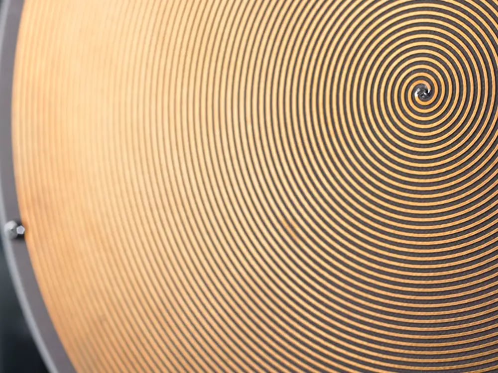
Fundamentals of RF system engineering
Various types of instruments are used in RF applications for measuring and analyzing RF signals. Spiral antennas, for example, are frequency-independent antennas used in wireless communications and applications that require large bandwidths of operation.
RF recording and replay
Recording signal activity 24/7, digitalizing it, and then analyzing it is extremely helpful for many areas, including spectrum management, RF system design, and communication security. Therefore, recording and replay solutions are necessary to record and store signal-capture data over long timeframes continuously.
RF systems complexity
Complexity is an essential consideration in designing, implementing, and maintaining RF systems and technologies.
RF systems complexity can be influenced by a variety of factors, including the number of frequency bands or channels, the required level of sensitivity, the types of modulation schemes used, the presence of interference, and the need for advanced signal processing techniques. As the demand for data bandwidth increases, so the methods for filtering, channel equalization and error control coding become more and more complicated and require greater processing power at both receiver and transmitter.
In general, as the number of frequency bands or channels and the level of sensitivity required increase, the complexity of the RF system also increases. For example, designing an RF system to operate over a wide frequency range or to detect weak signals in the presence of noise and interference is a complex task.
RF engineers and technicians need to be familiar with electromagnetic theory, antenna design, transmission line theory, RF propagation and RF circuit design to effectively design and maintain RF systems.

In the image above, light is being bent not unlike the modulation of an RF carrier signal.
Modulation
Modulation is the process of varying one or more properties of a high-frequency carrier signal to transmit information.
Several types of modulation are used in RF; however, the choice of modulation type depends on factors, including the specific application, the desired signal-to-noise ratio, and the available bandwidth.
- Amplitude Modulation (AM): the amplitude of the carrier signal is varied in proportion to the modulating signal, which typically contains the information to be transmitted. AM is a simple modulation commonly used for radio broadcasting.
- Frequency Modulation (FM): the frequency of the carrier signal is varied in proportion to the modulating signal. FM is commonly used in radio broadcasting and other applications requiring a high signal-to-noise ratio.
- Phase Modulation (PM): the phase of the carrier signal is varied in proportion to the modulating signal. PM is commonly used in digital communications systems, such as cellular networks and satellite communications.
- Quadrature Amplitude Modulation (QAM): a digital modulation technique that combines amplitude and phase modulation. QAM is commonly used in digital communications systems, such as cable modems, wireless networks, and satellite communications.
- Orthogonal Frequency-Division Multiplexing (OFDM): a digital modulation technique that divides the carrier signal into multiple subcarriers, each of which is modulated using QAM or another modulation type. OFDM is commonly used in high-speed wireless communications systems like Wi-Fi and 4G/LTE networks.
Carrier frequency and bandwidth
Carrier frequency and bandwidth are two different parameters.
Carrier frequency refers to the number of cycles of a waveform that occur in a second and is typically measured in Hertz (Hz). In RF, frequency is used to describe the rate at which a radio wave oscillates and is typically used to define a specific RF channel or frequency band. For example, the FM radio band in the United States spans from 88 to 108 MHz, which means that radio waves in this band oscillate between 88 and 108 million times per second.
Bandwidth refers to the range of frequencies that a modulated signal occupies. In RF, bandwidth is typically defined as the difference between the highest and lowest frequencies present in a modulated signal or channel. For example, a signal with a bandwidth of 10 kHz would occupy a frequency range from, say, 90 to 100 kHz.
In practical RF systems, the choice of carrier frequency and bandwidth is often a trade-off between factors such as available bandwidth, interference, power consumption, and regulatory requirements.
Emitters and receivers
Emitters generate and transmit RF signals, while receivers receive and demodulate RF signals.
Emitters include an RF oscillator, a modulator, and an RF amplifier. The RF oscillator generates a high-frequency carrier signal, which is then modulated with the information to be transmitted (such as voice, data, or video) using a type of modulation. The modulated signal is then amplified by the RF amplifier and transmitted through an antenna to the receiver.
Receivers include an antenna, an RF amplifier, a mixer, a local oscillator, a demodulator, and a low-pass filter. The antenna receives the RF signal and feeds it into the RF amplifier, amplifying the signal and filtering out interference. The mixer combines the amplified signal with a signal from the local oscillator, which generates a signal at a specific frequency. This process produces a signal at the intermediate frequency (IF), which is then demodulated to recover the original modulating signal. Finally, the low-pass filter removes any remaining high-frequency components, leaving only the original modulating signal.
In many RF systems, the emitter and receiver are combined. This carefully determined arrangement of components creates an exceptionally sensitive, high-performance single device—and allows for bidirectional communication between devices, such as in a mobile phone or a Wi-Fi router.
RF interference, spoofing, & jamming
RF interference, spoofing, and jamming are three critical issues that can disrupt wireless communication systems, posing a threat to their performance and reliability. As these problems have become increasingly prevalent, robust measures must be undertaken to mitigate their impact.
What is radio frequency interference?
RF signal interference is an interruption to a wireless connection caused by a nearby source of radio energy. This interference disrupts a device’s normal operation and can cause a decrease in performance or may even cause the device to fail. RF interference can come from a variety of sources, including other wireless devices, power lines, electrical equipment, and even weather conditions.
An unexpectedly poor SNR (signal-to-noise ratio) could be due to interference. If calculations have suggested a good SNR, but they do not match reality, it is important to establish why. Spectrum interference is ubiquitous; therefore, spectrum monitoring should establish the cause of the interference.
How to detect RF interference
RF interference is typically detected using specialized RF measurement equipment, such as RF Receivers and spectrum analyzers. These devices allow users to identify unwanted signals, view spectrum occupancy, localize the sources of interference, and establish how severe the interference is.
How to block RF interference
Depending on the source and type of interference, there are several ways to block or mitigate RF interference, including:
- Shielding, enclosing the source of the interference, or the sensitive equipment in a metal enclosure; and filtering, blocking specific frequencies or ranges of frequencies causing interference.
- Grounding, connecting the equipment to a grounded metal structure.
- Isolation, separating, or isolating sensitive equipment from potential sources of interference.
WHAT IS RF INTERFERENCE HUNTING?
RF interference hunting involves locating and identifying sources of RF interference that negatively affect wireless reception in a given area. The goal of RF interference hunting is to locate the source of the interferer, and then this information can be used to take appropriate measures to eliminate or mitigate it. This process can involve a variety of tools, including spectrum analyzers, directional antennas, signal generators, and interference mapping tools.
WHAT IS AN RF INTERFERENCE FILTER?
An RF interference (RFI) filter is an electronic device designed to block or attenuate unwanted signals or noise in the RF spectrum while permitting the desired signal. These devices use various filter technologies, such as low-pass, high-pass, band-pass, and band-stop filters. As well as filtering unwanted signals, RF interference filters also protect sensitive equipment from damage caused by high levels of RF energy.
HOW TO FIND AND FIX RF INTERFERENCE
- Identify the affected system or equipment that is experiencing interference.
- Determine the type of interference: is it narrowband, broadband, or intermittent?
- Investigate potential sources of interference, which could include other RF systems, electrical equipment, or natural phenomena like lightning.
- Conduct a site survey to assess the RF environment and identify any sources of interference.
- Use a spectrum analyzer to analyze the RF spectrum and identify any unwanted signals or noise.
- Check cables and connectors for damage or corrosion, which can affect the performance of the system.
- Verify the grounding and shielding, as inadequate grounding or shielding can lead to interference.
- Check the configuration of the affected system, such as the antenna height, orientation, and polarization.
- Install RF interference filters to block or attenuate unwanted signals or noise in the RF spectrum.
- Test and monitor the system to verify that the interference has been eliminated or mitigated. This may involve conducting field tests, performing signal quality measurements, or monitoring the system logs.
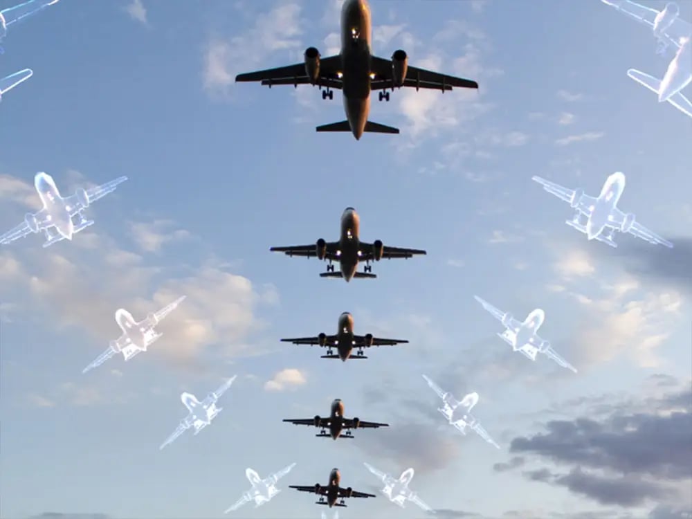
In this example, there is only one airplane; however, spoofing creates the impression there are far more airplanes.
WHAT IS RF SPOOFING?
RF spoofing is an attack that uses a transmitter to send a target receiver malicious signals, which differ from the true signals. The goal of RF spoofing is to disrupt the normal operation of a communication system. Sophisticated RF spoofing attacks can be particularly challenging to detect and prevent, as malicious signals are difficult to distinguish from normal ones.
WHAT IS RF SIGNAL EXFILTRATION?
RF signal exfiltration is a spying technique whereby RF signals are used to transmit sensitive or secret information out of a secure facility (such as an embassy).
Attackers do not need physical access to the target system and can operate from a distance. They can manipulate transmitted signals in various ways, such as changing signal strength, frequency, or modulation, to trick the receiver into accepting the fake signal as legitimate. This can allow the attacker to inject false data into the system, disrupt communications, or gain unauthorized access to the network.
Technical surveillance countermeasures are vital, particularly for sensitive environments such as embassies.
WHAT IS AN RF CYBER ATTACK?
An RF cyber attack can be either an intrusion or exfiltration attack, or both, using RF signals to carry out the attack.
For RF intrusion attacks, the attackers do not need physical access to the target system and can operate from a distance. They can manipulate transmitted signals in various ways, such as changing signal strength, frequency, or modulation, to trick the receiver into accepting the fake signal as legitimate. This can allow the attacker to inject false data into the system, disrupt communications, or gain unauthorized access to the network.
RF signal exfiltration is a spying technique whereby RF signals are used to transmit sensitive or secret information out of a secure facility (such as an embassy).
Technical surveillance countermeasures are vital, particularly for sensitive environments such as embassies, in order to counter RF cyber attacks.
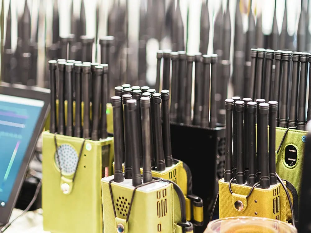
HOW DO YOU DETECT RF JAMMING?
One useful way to detect an RF jammer is by using a spectrum analyzer, which measures the strength of a signal in a given frequency range. Analyzing the signal strength in different parts of the spectrum can detect any interference blocking the signal, such as an RF jammer.
Common RF myths
Despite RF technology being pervasive in modern society and used in myriad devices, there are many myths surrounding it. Here are some of the most common.
Myth #1 – the more antennas a device has, the better it performs
This is not necessarily true. The number of antennas a device has only sometimes correlates with its performance. Other factors, such as the quality of the antenna, the design of the device, and the environment in which it’s being used, can also affect performance.
Myth #2 – you need line of sight to receive an RF signal
Not true. RF can successfully pass through many materials and can also transmit by reflection (e.g., ionosphere) or ‘RF Multipath’.
Myth #3 – better SDR performance is only attainable with large rack-mounted equipment
Not true. Today, some of the most sophisticated, high performance SDRs are low SWaP and capable of deployment across field troops, drones, pop-up masts, vehicles…with ease.
Myth #4 – RF sensors are complicated to operate
Not true. With automation and easy scheduling functions, operators can pre-plan missions, opening RF sensors to more users across multiple fields and multi (parallel) mission use.
Myth #5 – you always need high IP connections for remote spectrum systems
Not true. Sophisticated RF sensors can operate on low bandwidth communications and mesh networks, providing useful processed data perfect for contested spectrum environments.
RF testing
RF testing refers to the process of testing RF components and devices to ensure their proper functioning and compliance with regulatory standards. It is used to measure various parameters of RF devices, such as frequency, power, modulation, distortion, and noise.
RF testing is used in many fields, including telecommunications, electronics, aerospace, and defense. It is used to test various RF devices, such as antennas, transmitters, receivers, and amplifiers.
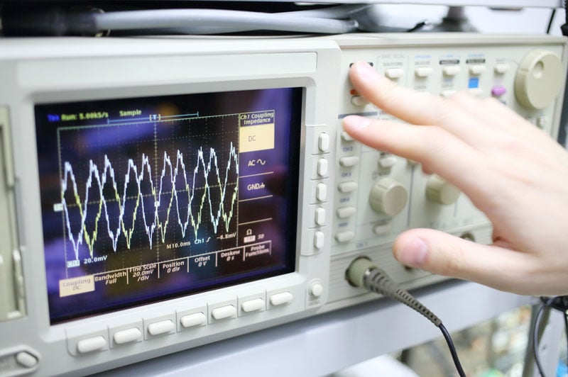
RF testing involves using specialized test equipment, including signal generators, spectrum analyzers, oscilloscopes, and power meters, to generate and measure RF signals. Testing may be performed under various conditions, including different frequencies, power levels, and environmental conditions, to ensure the device performs correctly in various scenarios.
Conclusion
Wireless technology is the invisible cornerstone of our modern world. We are completely dependent on wireless devices sending radio signals across the electromagnetic spectrum—all of which use RF transmission.
RF technology allows us to work, controls our transportation, and keeps us safe.
Therefore, gaining a deeper understanding of the RF technology that powers modern wireless communications systems, from Wi-Fi to cellular networks to satellite communications is paramount.
Expert RF hardware and software provides detailed data that will allow you to exploit the RF spectrum—optimize the performance of your RF systems, troubleshoot issues more effectively, and stay ahead of emerging trends and technologies in the field.